JS28F128P30B85 进口原装 INTEL
地区:广东 深圳
认证:
无
图文详情
产品属性
相关推荐
JS28F128P30B85
INTEL
TSSOP
08+
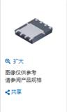
NTTFS5116PLTAG ON 安森美 进口原装 WDFN8 晶体管 MOSFET
PC28F256P30BFE MICRON FLASH存储器 进口原装
FDMS86200 MOSFET 150V N-Channel PowerTrench MOSFET
GD82551IT SL77C 只做进口原装 INTEL 以太网IC
MC74VHC4051DTR2G 多路复用开关 IC
LTV-354T-A LITEON 进口原装 SOP4 光电耦合器
LM339DR2G ON SOP 进口 放大器IC 模拟比较器
MC14081BDR2G ON 进口原装 SOP14 门极和反相器
MP2019GN-Z MPS SOP8 进口 电源管理IC 低压差稳压器 40V LQ Current Adj Output Linear Regula
S1M Liteon 台湾光宝 进口原装 特价 通用二极管 DO214 5Kpcs/盘