汽车电子点火电路 (ElectrONic car igniTIon)
click image for higher resolution
ATTENTION: Don't construct this project until this label is removed. There are some corrections that must be done in order to be full working. Sorry for the inconvenience.
Description:
This scheme is for 4 cylinder motor. This will make your car spent less fuel, be a little bit faster and you won’t have to frequently open your distributor cap to change the contact buttons thus wasting less money.
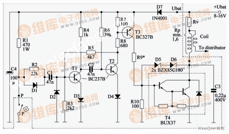
T1/T2 create one monostable multivibrator in which C2 and R5 determine the length of impulse which is 1,5 msec. Next in line are T3 and then T4 which is Darlington transistor specially developed for electronic ignition which is used as a switch to turn on/off primary coil. Impulses from switch P turn on monostable multivibrator T1/T2. You need to un-connect capacitor that is in distributor cap because it is not needed anymore. While switch P is closed T1 is in off state but T2 is in on state, also T3 and T4 which enables current to flow trough primary coil. When switch P is opened, T1 gets in on state for a moment causing C2 to charge over R6 which makes T2 go to off state because of voltage drop on R6. When T2 is off also T3 and T4 are off and current that was flowing trough primary coil is stopped. Because T2 is in off state, voltage on R8 is increased which is passed trough R5 on T1 base which is still in on state and C2 is still charging. After 1,5 msec. C2 value reaches the level where T2 goes to on state again and T1 goes to off state. Now T2, T3 and T4 are in on state, again, and current flows trough primary coil again. R2 and D1 are used to neutralize the effect of impulses caused from «jumping» of switch P which could turn on monostable multivibrator when it shouldn't.
Zener diodes Z5 and Z6 are together with R10 limit overcharged voltage impulses that are caused by self induction of primary coil which could damage T4. They should be connected as close as possible to T4.
D7 protects device from wrong polarity.
Coil should have ratio of 1:80 or 1:100 with external resistor Rv which is used for better cooling. Total resisting value (Rp) of primary coil and Rv resistor shouldn't be under 1,6 ohm's so current trough T4 wouldn’t be bigger than 10A.
Depending on Rp, R9 have different values:
120Ω/2W for Rp tot > 2,2Ω
100Ω/2W for 1,8Ω < Rp tot < 2,2Ω
82Ω/3W for 1,5Ω < Rp tot <1,8Ω
T4 has to be heatsinked!!!
All resistors are 1/2W +/-5%
Parts:
D1-D4 = 1N4148
D5-D6 = BZX85C – 180 (replicable with all equivalent types with power of 1,3W)
D7 = 1N4001
R1 = 470 - 1W
R2 = 22k
R3 = 2,2k
R4 = 1k
R5 = 4,7k
R6 = 39k
R7 – R10 = 100
R8 = 680
C1 – C2 = 47nF (ceramic)
C3 = 0,22uF 400V (ceramic)
C4 = 100uF (electrolytic)
T1 – T2 = BC327 (BC327-25, BC327-40)
T3 = BC237B (BC547B, BC547C)
T4 = BUX37 (BU323, BU920, BU921, BU922, BUV37B (u TOP3), BUW29, BUW81, MJ10012, MJ10013, MJ10014, TIP662, TIP665, 2SD683)
免责声明: 凡注明来源本网的所有作品,均为本网合法拥有版权或有权使用的作品,欢迎转载,注明出处。非本网作品均来自互联网,转载目的在于传递更多信息,并不代表本网赞同其观点和对其真实性负责。