Assemble by soldering the components to the pads indicated. Keep coil, resistor, and capacitor leads as short as possible. The coils should be 3/16" to 1/4" above the board and separate turns by one wire diameter. Bend leads to form a little mounting foot for soldering to the circuit board. Tuning and power output are affected by the distance between the coil turns, you can make fine adjustments by either spreading or compressing the coil slightly. The area surrounding the pads is ground. C2, C3, C4, C6, C7, C8, C9, C10, L2, and R1 are soldered at one end to ground as well as the shield braid on the coax cables. Bolt Q1 to a small heat sink or the chassis with heat sink thermal compound or gray thermal pad underneath the tab. With an input level of 200-500mw, you should see an output of 5-6 watts. Be sure to have a proper dummy load (50 ohms) or tuned antenna connected to the output, doing otherwise will likely destroy the transistor. 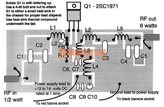
Parts List
| 2 | 470 pF mica capacitor | C1, C5 |
| 1 | 75 pF mica capacitor | C2 |
| 1 | 39 pF mica capacitor | C3 |
| 1 | 12 pF mica capacitor | C4 |
| 2 | 0.001 uF disc or monolythic capacitor (marked either 102, .001, or 1n) | C6, C8 |
| 2 | 0.1 uF disc or monolythic capacitor (marked either 104, .1, or 100n) | C7, C9 |
| 1 | 10 to 22 uF electrolytic capacitor (observe correct polarity) | C10 |
| 1 | 1 turn #18 tinned copper, 1/4" dia. | L1 |
| 1 | 1 uH inductor, blue lumpy item | L2 |
| 1 | 2 turns #18, 1/4" dia. | L3 |
| 1 | 7/10" #14, hairpin | L4 |
| 2 | 5 turns #20, 1/4" dia. | L5, L6 |
| 1 | 56 ohm resistor with ferrite bead over lead at the base of end of Q1 | R1 |
| 1 | 2SC1971 RF transistor | Q1 |
| 2 | SO239 socket | |
| 2 | banana plug (1 each red and black) | |
| 2 | banana socket (1 each red and black) | |
| 1 | ferrite bead | |
| 4 | 4-40 nuts | |
| 4 | 4-40 bolts | |
| RG174 coaxial cable | ||
| hookup wire | ||
| soldering lugs |
免责声明: 凡注明来源本网的所有作品,均为本网合法拥有版权或有权使用的作品,欢迎转载,注明出处。非本网作品均来自互联网,转载目的在于传递更多信息,并不代表本网赞同其观点和对其真实性负责。