供应二手E5062A ENA-L 射频网络分析仪
地区:四川 成都
认证:
无
图文详情
产品属性
相关推荐

成都市美蓝电子仪器有限公司(深美蓝电子科技成都分公司)
吕小霞:13540277872座机:028-85059708-811
贸易通:szpotence QQ: 传真:
:@qq.com 网址:www.shenmeilan.com
地址:成都武候区武科东三路9号康特园6栋610-613室
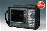
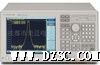
E5062A ENA-L 射频网络分析仪,300 kHz 至 3 GHz
E5062A 通用网络分析仪采用现代*新的技术,具有易于使用的特性和稳定的性能,从而能够进行*的基础 S 参数测量。
 主要技术指标
Agilent
ENA-L RF Network Analyzers
E5061A, 300 kHz to 1.5 GHz
E5062A, 300 kHz to 3 GHz
Data Sheet
2
All specifications apply over a 23 °C &plu*n;5 °C range (unless otherwise stated)
and 90 minutes after the instrument has been turned on.
Specification (spec.):
Warranted performance. Specifications include guardbands to account for the
expected statistical performance distribution, measurement uncertainties, and
changes in performance due to environmental conditions.
Supplemental information is intended to provide information that is helpful
for using the instrument but that is not guaranteed by the product warranty.
T*ical (t*.):
Describes performance that will be met by a minimum of 80% of all products.
It is not guaranteed by the product warranty.
Supplemental performance data (SPD):
Represents the value of a parameter that is most likely to occur; the expected
mean or average. It is not guaranteed by the product warranty.
General characteristics:
A general, descriptive term that does not imply a level of performance.
Definitions
3
Corrected system performance
The specifications in this section apply for measurements made with the
Agilent E5061A/E5062A network *yzer with the following conditions:
• No averaging applied to data
• Environmental temperature of 23 °C &plu*n;5 °C, with less than 1 °C deviation
from the calibration temperature
• Response and isolation calibration not omitted
Table 1-1 System dynamic range1 2
Description Specification SPD
System dynamic range
300 kHz to 1 MHz, IF bandwidth = 3 kHz 90 dB
1 MHz to 3 GHz, IF bandwidth = 3 kHz 95 dB
300 kHz to 1 MHz, IF bandwidth = 10 Hz 115 dB
1 MHz to 3 GHz, IF bandwidth = 10 Hz 120 dB 130 dB
1. The test port dynamic range is calculated as the difference between the test port rms noise floor
and the source maximum output power. The effective dynamic range must take measurement
uncertainty and interfering signals into account.
2. Applicable to the units with serial prefix MY442 and above .
System dynamic range; specification and measurement example
System dynamic range
80
90
100
110
120
130
140
150
160
3.0E+05 5.0E+08 1.0E+09 1.5E+09 2.0E+09 2.5E+09
Test frequency [/Hz]
System dynamic range [/dB]
E5061A/62A spec.
4
Table 1-2 Corrected system performance with T*e-N 50 Ω connectors,
85032F calibration kit, full 2-port calibration
Network *yzer: E5061A/E5062A, calibration kit: 85032F (T*e-N, 50 Ω), calibration: full 2-port
I F bandwidth = 10 Hz, No averaging applied to data, environmental temperature = 23 °C &plu*n;5 °C
with < 1 °C deviation from calibration temperature, isolation calibration not omitted
Description Specification (dB)
300 kHz to 1.5 GHz 1.5 to 3 GHz
Directivity 49 46
Source match 41 40
Load match 49 46
Reflection tracking &plu*n;0.011 &plu*n;0.021
Tran*ission tracking &plu*n;0.015 &plu*n;0.018
Tran*ission uncertainty (specification)
Magnitude Phase
Reflection uncertainty (specification)
Magnitude Phase
5
Table 1-3 Corrected system performance with T*e-N 50 Ω connectors,
85032F calibration kit, enhanced response calibration
Network *yzer: E5061A/E5062A, calibration kit: 85032F (T*e-N, 50 Ω) calibration: enhanced
response
IF bandwidth = 10 Hz, no averaging applied to data, environmental temperature = 23 °C &plu*n;5 °C with
< 1 °C deviation from calibration temperature, isolation calibration not omitted
Description Specification (dB)
300 kHz to 1.5 GHz 1.5 to 3 GHz
Directivity 49 46
Source match 41 40
Load match 15 15
Reflection tracking &plu*n;0.011 &plu*n;0.021
Tran*ission tracking &plu*n;0.015 &plu*n;0.018
Tran*ission uncertainty (specification)
Magnitude Phase
Reflection uncertainty (specification)
Magnitude Phase
6
Table 1-4 Corrected system performance with T*e-N 75 Ω connectors
85036E calibration kit, full 2-port calibration
Network *yzer: E5061A/E5062A, calibration kit: 85036E (T*e-N, 75 Ω), calibration: full 2-port
IF bandwidth = 10 Hz, no averaging applied to data, environmental temperature = 23 °C &plu*n;5 °C with
< 1 °C deviation from calibration temperature, isolation calibration not omitted
Description Specification (dB)
300 kHz to 1.5 GHz 1.5 to 3 GHz
Directivity 48 44
Source match 41 35
Load match 48 44
Reflection tracking &plu*n;0.010 &plu*n;0.019
Tran*ission tracking &plu*n;0.015 &plu*n;0.029
Tran*ission uncertainty (specification)
Magnitude Phase
Reflection uncertainty (specification)
Magnitude Phase
7
Table 1-5 Corrected system performance with T*e-N 75 Ω connectors
85036E calibration kit, enhanced response calibration
Network *yzer: E5061A/E5062A, calibration kit 85036E (T*e-N, 75 Ω), calibration: enhanced response
IF bandwidth = 10 Hz, no averaging applied to data, environmental temperature = 23 °C &plu*n;5 °C with
< 1 °C deviation from calibration temperature, isolation calibration not omitted
Description Specification (dB)
300 kHz to 1.5 GHz 1.5 to 3 GHz
Directivity 48 44
Source match 41 35
Load match 15 15
Reflection tracking &plu*n;0.010 &plu*n;0.019
Tran*ission tracking &plu*n;0.015 &plu*n;0.029
Tran*ission uncertainty (specification)
Magnitude Phase
Reflection uncertainty (specification)
Magnitude Phase
8
Table 1-6 Uncorrected system performance
(correction: off, 23 °C &plu*n;5 °C)
Description Specification
300 kHz to 3 GHz
Directivity 25 dB
Source match 25 dB
Load match 15 dB
Tran*ission tracking &plu*n;1.0 dB
Reflection tracking &plu*n;1.0 dB
Table 1-7 Test port output frequency
Description Specification T*ical
Range
E5061A 300 kHz to 1.5 GHz
E5062A 300 kHz to 3 GHz
Resolution 1 Hz
Source stability
E5061A/E5062A &plu*n;5 ppm (5 °C to 40 °C)
CW accuracy
E5061A/E5062A &plu*n;5 ppm, 23 °C &plu*n;5 °C
Uncorrected system performance
Test port output (source)
9
Table 1-9 Test port output signal purity
Description Specification T*ical
Harmonics (2nd or 3rd)
10 MHz to 2 GHz < –25 dBc (at 5 dBm)
Non-harmonic spurious
10 MHz to 3 GHz < –30 dBc (at 0 dBm)
Test port output (source)
Table 1-8 Test port output power
Description Specification T*ical
Level accuracy (at 23 °C &plu*n;5 °C)1
300 kHz to 3 GHz &plu*n;0.8 dB (at 0 dBm, 50 MHz absolute)
&plu*n;1.0 dB (at 0 dBm, relative
to 50 MHz reference)
Level linearity (at 23°C &plu*n;5°C)
300 kHz to 3 GHz &plu*n;0.75 dB (at –5 to 10 dBm)
Range (standard)
300 kHz to 3 GHz –5 to 10 dBm
Range (extended power)
300 kHz to 3 GHz –45 to 10 dBm (non-harmonics spurious may limit power range)
Sweep range (without extended power range)
300 kHz to 3 GHz –5 to 10 dBm
Level resolution 0.05 dB
Test port output (source)
1. Level accuracy for 75Ω *yzers is not a specification for frequencies >2 GHz; it is a t*ical characteristic.
10
Table 1-10 Test port input levels
Description Specification T*ical
Maximum test port input level
300 kHz to 3 GHz +10 dBm
Damage level
300 kHz to 3 GHz +20 dBm, &plu*n;30 VDC
Crosstalk1
300 kHz to 3 GHz –110 dB
Table 1-11 Test port input (trace noise2)
Description Specification T*ical
Trace noise magnitude
300 kHz to 1 MHz 8 mdB rms (23 °C &plu*n;5 °C)
(source power level = +10 dBm)
1 MHz to 3 GHz 5 mdB rms (23 °C &plu*n;5 °C)
(source power level = +10 dBm)
Trace noise phase
300 kHz to 1 MHz 0.05° rms (23 °C &plu*n;5 °C)
(source power level = +10 dBm)
1 MHz to 3 GHz 0.03° rms (23 °C &plu*n;5 °C)
(source power level = +10 dBm)
Test port input
1. Response calibration not omitted.
2. Trace noise is defined as a ratio measurement of a through, at IF bandwidth = 3 kHz.
3. Stability is defined as a ratio measurement at the test port.
Table 1-12 Test port input (stability 3)
Description Specification T*ical
Stability magnitude
3 MHz to 3 GHz 0.01 dB/°C
(at 23 °C &plu*n;5 °C)
Stability phase
3 MHz to 3 GHz 0.1°/°C
(at 23 °C &plu*n;5 °C)
11
Table 1-13 Test port input (dynamic accuracy)
Accuracy of the test port input power reading is relative to –10 dBm reference input power level.
Specification T*ical
Magnitude Phase
12
Table 1-14 Test port input (group delay 1)
Description Specification Supplemental information
Aperture (selectable) (frequency span)/(number of points –1)
Maximum aperture 25% of frequency span
Minimum delay Limited to measuring no more than
180° of phase change within the minimum aperture.
Accuracy See graph below
The following graph shows group delay accuracy with T*e-N full 2-port calibration and a 10 Hz IF bandwidth. Insertion loss is *umed to be < 2 dB.
Group delay (t*ical)
In general, the following formula can be used to determine the accuracy, in seconds, of specific group delay measurement:
&plu*n;phase accuracy (deg)/[360 x aperture (Hz)]
1. Group delay is computed by measuring the phase change within a specified step (determined by the
frequency span and the number of points per sweep).
13
Table 1-15 System bandwidths
Description General characteristics
IF bandwidth settings
Range 10 Hz to 30 kHz
Nominal settings are:
10, 30, 100, 300, 1 k, 3 k, 10 k, 30 k
Table 1-16 Front panel information
Description General characteristics
RF connectors
T*e T*e-N, female; 50 Ω or 75 Ω
Display
Size 10.4 in TFT color LCD
Resolution VGA (640 x 480)1
General information
1. Valid pixels are 99.99% and more. Below 0.01% of fixed points of black, blue, green or red are
not regarded as failure.
14
Table 1-17 Rear panel information
Description General characteristics
External trigger connector
T*e BNC, female
Input level LOW threshold voltage: 0.5 V
HIGH threshold voltage: 2.1 V
Input level range: 0 to +5 V
Pulse width ≥ 2 μsec
Polarity Negative (downward) only
External reference signal input connector
T*e BNC, female
Input frequency 10 MHz &plu*n;10 ppm
Input level 0 dBm &plu*n;3 dB
Internal reference signal output connector
T*e BNC, female
Output frequency 10 MHz &plu*n;10 ppm
Signal t*e Sine wave
Output level 0 dBm &plu*n;3 dB into 50 Ω
Output impedance 50 Ω
VGA video output 15-pin mini D-Sub; female; drives VGA compatible monitors
GPIB 24-pin D-Sub (t*e D-24), female; compatible with IEEE-488
Parallel port 36-pin D-Sub (t*e 1284-C), female; provides connection to printers, or multiport
test set
U* port Universal serial bus jack, t*e A configuration (4 contacts inline, contact 1 on left);
female; provides connection to printer, ECal module, U*/GPIB interface
Contact 1 Vcc: 4.75 to 5.25 VDC, 500 mA, maximum
Contact 2 -Data
Contact 3 +Data
Contact 4 Ground
LAN 10/100 BaseT Ethernet, 8-pin configuration; auto selects between the two data rates
Handler I/O port 36-pin Centronics, female; provides connection to handler system
Line power1
Frequency 47 Hz to 63 Hz
Voltage 90 to 132 VAC, or 198 to 264 VAC (automatically switched)
VA max