|
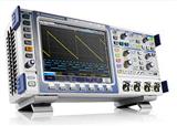
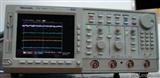
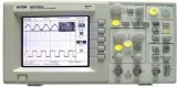
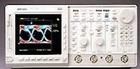
模拟示波器 V-1060
100MHz/2mv/5ns/2通道/CRT读出
厂家: 日本日立
尺寸: 27×13×45cm
重量: 4kg
The Hitachi portable read-out oscilloscope provides measure-ment reliability and ease of operation by employing amicroprocessor.
The major features are:
(1) Measurement information display
The measurement information including the sweep speed, thedelay time, the IJNCAL display, and the voltage sensitivity ofthe vertical axis (V-1065 ,V-1065C and V-665 only) is alpha-numerically displayed on the CRT.
Since troublesome setting operation procedures are eliminat-ed, an operator can concentrate on the displayed data formeasurement.
(2) Measurement value display (V-1065, V-1065C, V-665 only)
The distance between the two cursors displayed can read out the following;
△V : Voltage between the reference cursor and the deltacursor
△T : Time between the reference cursor and the deltacursor
1/△T: Reciprocal of the time
The displayed data eliminates troublesome and time consumingcalculation procedures. Moreover, miscalculation of thescales is compley avoided.
(3) Automatic time base range setting
At a press of the AUTO button, an optimum time base range is automatically set.(A signal period from 1.6 to 4 cyclesapprox. is displayed.)The time base range is automatically changed to a correspond-ing change in input signal period.
(4) Trigger lock
Since complicated pulse train waveforms are hard to trigger on, performing the trigger lock function enables sweep independent triggering. The "sweep time plus holdoff time"is fixed and a stable trigger is obtained at any time range.
(5) Bandwidth
V-1065,V-1065C,: DC-100 MHz from 5 V/div to S mv/div
V-1060 DC-20 MHz at 2 mV/div
V-665, V-660 : DC-60 MHz from 5 V/div to S mv/div
(6) High sensitivity
DC-10 MHz at 2 mv/divHigh sensitivity of 2 mV/div is provided.
(7) Internal graticule
Internal graticule lines eliminate parallax-viewing errorbetween the trace and the graticule lines.
(8) Delayed sweep
With delayed sweep, a portion of the signal can be magnifined for more accurate measurement and the windows of delayed sweep(B) is indicated on the main sweep(A) with cursors.
(9)Auto trigger level
Auto measuring of trigger level is employed, so that trigger level range is mathed to the trigger signal for maximum trigger sensitivity and stability.
(10)TV triggering
Exclusive TV sync separator circuit technology provides stable TV signal measurements on fields, frames and lines.
Specifications
(A) Frequency counter
1.1 Specifications
Measuring signal : Measure the signal selected as atrigger signal by the TRIG SOURCEOR X switch.
Measuring range : 20 Hz to 100 MHz
Accuracy of reference signal : 100 ppM (15 to 35°C)
|
Measuring range
|
Display format
|
Resolution
|
Accuracy
|
|
20Hz≤f<100Hz
|
99.99Hz
|
0.01Hz
|
Ref.signal ±1 LSD
|
|
100Hz≤f<1kHz
|
999.9Hz
|
1.0Hz Max
|
|
1kHz≤f<10kHz
|
9.999Hz
|
0.002Hz Max
|
|
10kHz≤f<100kHz
|
99.99Hz
|
0.04Hz Max
|
|
100kHz≤f<1MHz
|
999.9Hz
|
0.1Hz
|
|
1MHz≤f<10MHz
|
9.999Hz
|
0.002Hz Max
|
|
10MHz≤f<100MHz
|
99.99Hz
|
0.01Hz
|
|
100MHz≤f
|
(999.9Hz)
|
Not specified
|
1 .2 Frequency measurement
When MEASURE is selected by the SELE*OR switch, the * cursor is displayed on CRT. Then press the SELE*OR switchthree times to display FREQ at the upper part of CRT.
The frequency counter is interlocked with the triggering andthe measurement starts from the triggering point.
Consequently, any special frequency having complex waveformscan be measured by changing the trigger level.
For example, when a signal as illustrated below is applied,the frequency of the entire waveforms can be measured whentriggered at point A. When triggered at point B, thefrequency of a pulse with large amplitude can be measured.
Note : When not triggered, the measurement can not be per-formed, since the counter is interlocked with thetriggering. In the non-triggering mode or in case ofthe input signal less than 20 Hz, the message"FREQ..." is displayed.
(B) Memory backup
The panel setting data is retained for move than 48 hoursafter turning off power. It is not needed to perform thesame panel settings again even on the day after tomorrow.
(C) Other specifications
Same with those of the V-1065.
|
|
V-1065/V-1065C
|
V-1060
|
V-665
|
V-660
|
|
●CRT
|
|
|
|
|
|
Graticule
|
6-inch screen with internal graticule 0%, 10%, 90% and 100% markers
8x10 DIV(1DIV=1cm)
|
|
|
|
|
Phosphor
|
P31
|
|
|
|
|
Accelerating potential
|
17kV approx.
|
|
12kV approx.
|
|
|
External intensity modulation
|
Coupling: DC coupling
Voltage: 5V or more
Maximum input voltage: 30V (DC+AC peak)
or 30Vp-p AC at 1kHz or less
Bandwidth: DC to 5MHz
|
|
|
|
|
●Vertical deflection system
|
|
|
|
|
|
Sensitivity
|
2mV/DIV to 5V/DIV ±3%(switchable in 11 steps) Continuously variable
|
|
|
|
|
Bandwidth
|
DC to 100MHz -3dB
2mV/DIV: DC to 20MHz -3dB
AC low p*: 10Hz
|
|
60MHz
10MHz
|
|
|
Rise time
|
3.5 ns apporx.
2mV/DIV: 17.5 ns approx.
|
|
5.9ns approx.
|
|
|
Delay time
|
Leading edge can be monitoed
|
|
35ns approx.
|
|
|
Maximum input voltage
|
400V(DC+AC peak)at 1 kHz or less
|
|
|
|
|
Input coupling
|
AC, DC, GND
|
|
|
|
|
Input impedance
|
1M ohms ±1.5%, 23pF ±3pF
|
|
|
|
|
Display modes
|
CH1, CH2, DUAL, CHOP(250kHz approx.),ADD(DIFF mode can be established when the CH2 is in the INVERT mode.)
|
|
|
|
|
Bandwidth limiting function
|
20MHz
|
|
10MHz
|
|
|
Polarity selection
|
±(CH2 only)
|
|
|
|
|
Common-mode rejection ratio
|
20dB minimum at 20MHz
|
|
|
|
|
X-Y operation
|
X-axis, Y-axis selectable
|
|
|
|
|
Sensitivity
|
X axis:
CH1, CH2 2mV to 5V/DIV ±3%
EXT 0.1V/DIV ±5%
EXT÷10 1V/DIV ±5%
Y axis: 2mV to 5V/DIV ±5%
|
|
|
|
|
Phase error
|
3°or less from DC to 50 kHz
|
|
|
|
|
X bandwidth
|
DC to 500 kHz(-3dB)
|
|
|
|
|
●Horizontal deflection system
|
|
|
|
|
|
Trigger mode
|
Trigger,auto trigger
|
|
|
|
|
Sweep mode
|
Main sweep, continous delay sweep, alternate sweep, signal sweep
|
|
|
|
|
Trigger source
|
CH1, CH2, EXT(AC,DC,DC÷10),LINE
|
|
|
|
|
TV trigger
|
Excusive sync separtor circuit provided Sync polarity:-
|
|
|
|
|
Trigger Sensitivity
|
|
|
|
|
|
*RM mode
|
|
Frequence
|
DC to 20MHz
|
20MHz to 100MHz
|
|
INT
|
0.35 DIV
|
1.5 DIV
|
|
EXT
|
50 mV
|
150 mV
|
|
|
DC to 10MHz
10MHz-60MHz
|
|
|
AUTO mode
|
|
Frequence
|
30 to 100Hz
|
100Hz to 20MHz
|
20 to 100MHz
|
|
INT
|
1.5 DIV
|
1 DIV
|
1.5 DIV
|
|
EXT
|
150 mV
|
100 mV
|
150 mV
|
|
|
30 to 100Hz
100Hz-10MHz
10-60MHz
|
|
|
TV mode
|
Sync signal
Internal sync: 1div or more
External sync: 200mVp-p or more
|
|
|
|
|
Trigger level
|
Variable range
AUTO: Automatically corresponds to the trigger signal
*RM: INT: ±4 DIV or more
EXT: ±0.4 V or more
EXT÷10:±4V or more
|
|
|
|
|
External input impedance
|
1 M ohms ±5%, 25pF + 6pF
|
|
|
|
|
External input voltage
|
400V(DC+AC peak) at 1kHz
|
|
|
|
|
Sweep time
|
|
|
|
|
|
A(main) sweep
|
50 ns/DIV to 0.5 s/DIV Continuously variable (UNCAL)
|
|
|
|
|
B(delay) sweep
|
50 ns/DIV to 50 ms/DIV
|
|
|
|
|
Accuracy
|
|
|
10 to 35℃
|
0 to 50℃
|
|
X1
|
±3%
|
±4%
|
|
MAG X10
|
±4%
|
±6%
|
|
|
|
|
|
Sweep magnification
|
X10
|
|
|
|
|
Maximum sweep rate
|
5 ns/DIV
|
|
|
|
|
Hold off time
|
Variable
|
|
|
|
|
Delay time
|
1μs to 5s
|
|
|
|
|
Delay jitter
|
1/20,000 or less
|
|
|
|
|
Alternate separation
|
Variable
|
|
|
|
|
Trigger lock function
|
Provided
|
|
|
|
|
Auto range function
|
Provided
|
|
|
|
|
Singnal sweep function
|
Provided
|
|
|
|
|
●Readout funtion
|
|
|
|
|
|
Pannel setting display
|
Vertical axis: V/DIV(CH1,CH2),UNCAL,probe conversion
Sweep speed: S/DIV,UNCAL,MAG(converted value)
Other: Delay time
|
Not provided
|
Same as V-1065
|
Not provided
|
|
●Cursor readout function
|
Voltage difference △V: △-REF
Time difference △T: △-REF
Frequency 1/△T: △-REF
|
No cursor
|
Same as V-1065
|
No cursor
|
|
●External output
|
|
|
|
|
|
TRIGGER SIGNAL OUT
|
Output voltage: 25mV/DIV approx.
(Full scale on the CRT)
50-ohm termination
Frequency response: DC to 10MHz
Output impedance: 50 ohms approx.
|
Not provided
|
Same as V-1065
|
Not provided
|
|
●Calibrator
|
|
|
|
|
|
Waveform
|
1kHz ±20%, square wave
|
|
|
|
|
Voltage
|
0.5V ±1%
|
|
|
|
|
●Power supply
|
90V to 250V AC, 48 to 440Hz, 40W approx.
|
|
|
|
|
●Other
|
|
|
|
|
|
Dimensions
|
275(W) x 130(H) x 360(D) mm
|
|
|
|
|
Weigth
|
6kg
|
|
|
|
|
EMI
|
VDE0871, Category B
|
|
|
|
|