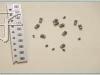
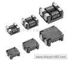
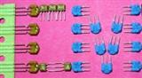
Ceramic Bandp* Filters (Array T*e,Monoblock T*e,300Mhz~4Ghz)
|
Features: Custom design,High consistent Q Extremely Temperature stable,Low insertion loss Low cost,fast delivery Applications: 3G,4G telecommunication Base station of GSM,CDMA,Wimax,WIfi,3G,4G Spectrum *yzer,RF transceivers Repeater of GSM,CDMA,Wimax,Wifi,PCS, WLL,ISM,CATV,GPS Cellular systems Remote metering,Global positioning,switch-filters GPS/Glon* equipment Global Navigation Satellite System(GLONASS) Satellite communication Dimension: 3mm , 4mm , 5mm , 6mm , 8mm,Custom design available Configuration Array t*e dielectric filter and monoblock t*e with 2,3,4,5,6,8,10 poles |
We can offers Ceramic Bandp* Filters(also called dielectric filters, or dielectric ceramic filters,microwave ceramic filters) in standard resonator sizes of 2mm , 3mm , 4mm , 5mm , 6mm , 8mm , 10mm and 12mm (normally 3mm , 4mm , 5mm , 6mm , 8mm ). Bandwidth: 0.5% to 8% of center frequency Basic rules of ceramic band-p* filters and diplexersp The higher the Q-factor of a resonators/band p* filters,the better electrical performance for insertion loss. The more dielectric resonators combined together for a band p* ceramic filters, the better rejection/attenuation/s*band will be. Determinant factor for Insertion Loss Q factor of a resonator, the bandwidth of a filter, and the number of resonators Determinant factor for Attenuation/rejection The number of resonators, connection t*e of resonators |