current, further include a short circuit protector for preventing large external short circuit current.
Each of these ICs is composed of three voltage detectors, a reference unit, a delay circuit, a short circuit protector, and a l
ogic
circuit. When charging voltage crosses the detector threshold from a low value to a value higher than V
DET1
, the output of C
OUT
pin, the output of over-charge detector/VD1, switches to low level, charger's negative pin level. After detecting over-charge t disconnected from the battery pack while the V
DD
level is in
between “V
DET1
” and “V
REL1
” in the R5421NxxxC/F version.
The output of D
OUT
pin, the output of over-discharge detector/VD2, switches to low level after internally fixed delay time
passed, when discharging voltage crosses the detector threshold from a high value to a value lower than V
DET2
.
After R5421NxxxC/F Series detect the over-discharge voltage, connect a charger to the battery pack, and when the battery
supply voltage becomes higher than the over-discharge detector threshold, VD2 is released and the voltage of D
OUT
becomes
“H” level. In the case of F version, after detecting the over-discharge detection, when the battery supply
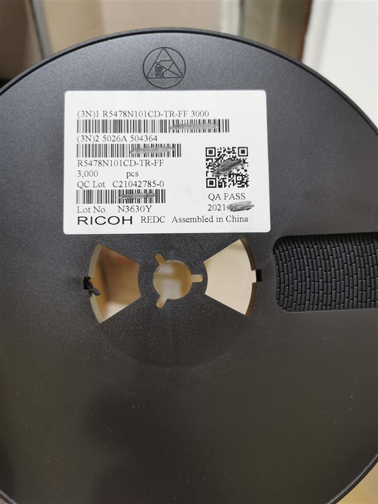
 供应R5478N101CD-TR-FF锂电池管理保护 CD
