TLP320

TLP320


Telecommunication
Office Machine
Telephone Use Equipment
The TOSHIBA TLP320, −2 and −4 consists of a photo−transistor
optically coupled to a gallium arsenide infrared emitting diode.
The TLP320−2 offers two isolated channels in an eight lead plastic DIP
package, while the TLP320−4 provides four isolated channels in a
sixteen plastic DIP package. This is suitable for application of AC input
current up to 150mA.
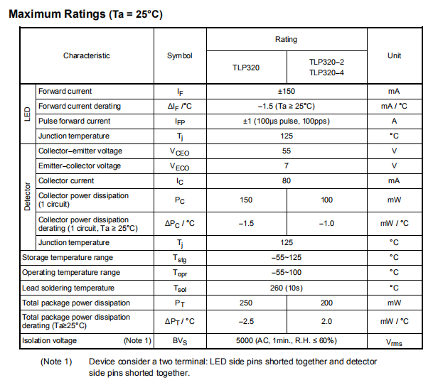
�� IF maximum rating: ±150mA
�� Collector−emitter voltage: 55V (min.)
�� Current transfer ratio: 25% (min.) (IF = 20mA)
�� Isolation voltage: 5000Vrms (min.)
�� UL recognized: file No. E67349
Isolation Characteristics (Ta = 25°C)
Characteristic Symbol Test Condition Min. Typ. Max. Unit
Capacitance input to output CS
VS = 0, f = 1 MHz — 0.8 — pF
Isolation resistance RS
VS = 500 V, R.H. ≤ 60% 5×10¹⁰
1014
—
Ω
AC, 1 minute 5000 — —
AC, 1 second, in oil — 10000 —
Vrms
Isolation voltage BVS
DC, 1 minute, in oil — 10000 — Vdc
Switching Characteristics (Ta = 25°C)
Characteristic Symbol Test Condition Min. Typ. Max. Unit
Rise time tr
— 2 —
Fall time tf
— 3 —
Turn�on time ton
— 3 —
Turn�off time toff
VCC = 10 V, IC = 2 mA
RL = 100Ω
— 3 —
μs
Turn�on time tON
— 2 —
Storage time ts
— 15 —
Turn�off time tOFF
RL = 1.9 kΩ (Fig.1)
VCC = 5 V, IF = ±16 mA
— 25 —
μs
Coupled Electrical Characteristics (Ta = 25°C)
Characteristic Symbol Test Condition Min. Typ. Max. Unit
IC / IF
IF = ±20 mA, VCE = 1 V 25 — —
Current transfer ratio
IC / IF
(high)
IF = ±100 mA, VCE = 1 V 20 — 80
%
IC = 2.4 mA, IF = ±20 mA — — 0.4
Collector�emitter
saturation voltage
VCE (sat)
IC = 2.4 mA, IF = ±100 mA — — 0.4
V
Off�state collector current IC(off) VF = ± 0.7V, VCE = 24 V — 1 10 μA
CTR symmetry (Note) IC (ratio)
IC (IF = �20mA) /
IC (IF = +20mA) (Note)
0.5 1 2 —


