图文详情
产品属性
相关推荐
 y
y
Application Information
Capacitor Selection and Regulator
Stability
Input Capacitor
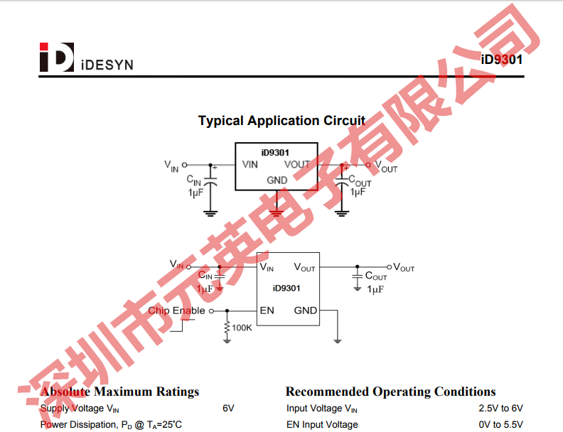
An input capacitance of 1μF is required between the
device input pin and ground directly (the amount of the
capacitance may be increased without limit). The input
capacitor MUST be located less than 1 cm from the
device to assure input stability (see PCB Layout
Section). A lower ESR capacitor allows the use of less
capacitance, while higher ESR type (like aluminum
electrolytic) requires more capacitance. Capacitor
types (aluminum, ceramic and tantalum) can be mixed
in parallel, but the total equivalent input
capacitance/ESR must be defined as above for stable
operation. There are no requirements for the ESR on
the input capacitor, but tolerance and temperature
coefficient must be considered when selecting the
capacitor to ensure the capacitance is 1 μF over the
entire operating range.
Output Capacitor
The iD9301 is designed specifically to work with very
small ceramic output capacitors. The minimum
capacitance recommended (temperature
characteristics of X7R, X5R, Z5U or Y5V) is within the
1μF to 10μF range with 5mΩ to 50mΩ ESR range
ceramic capacitor between LDO output and GND for
transient stability, but it may be increased without limit.
Higher capacitance values help to improve transient
response. The output capacitor's ESR is critical
because it forms a zero to provide phase lead which is
required for loop stability.
Enable Function
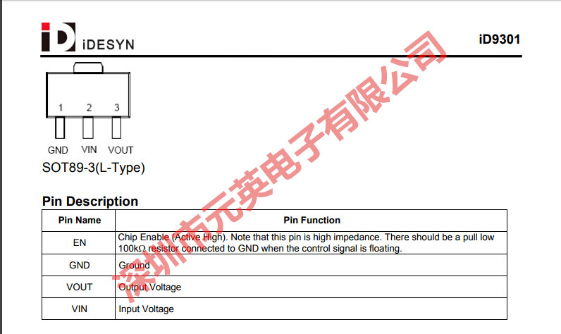
The iD9301 is shut down by pulling the EN pin low, and
turned on by driving the input high. If the shutdown
feature is not required, the EN pin should be tied to
VIN to keep the regulator on at all times (the EN pin
MUST NOT be left floating).
iDESYN/益力
SOT23-3
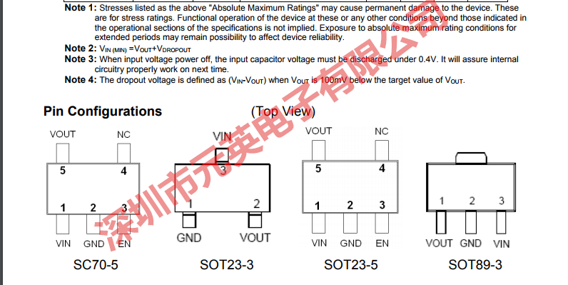
后缀不同封装不同,咨询请发完整型号
2500