图文详情
产品属性
相关推荐

...............................................................................................................................................................................................................................................................................................................................................................................................................................................................................................................................
*,同等质量,价格*
*产品满500元包邮
一等材质,工业级品质,库存充足,*频点可定制


![]()
一、 基础理论
1、 水晶的分子式:SiO2
2、 水晶的硬度:莫氏硬度7级
3、 水晶的比重: 2.65
4、 一个完整的天然水晶一共有30个面,共分5组,每组 6个。
5、 水晶有几个二次对称轴?3个
6、 X轴称为电轴,Y轴称为机械轴,Z轴称为光轴。
7、 公司产品*常用的是那种切型?AT
8、 公司产品属于哪种基本振动模式? 厚度剪切
9、 温度* 573 度,*做晶体元件。
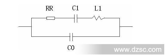
10、 画出晶体元件的等效电路图:

二、 名词解释:
1、标称频率F0:客户给定的频率或是标识频率
2、负载谐振频率FL:带负载电容时测量的频率
3、负载电容CL:产品生产时所串的频率(线路晶体两端串联电容与分布电容的和)
4、调整频差△FL=FL-F0:用户要求的频率误差范围或是电路上可以调整的频率范围
5、谐振电阻RR:晶体工作时的等效电阻
6、负载谐振电阻RL:晶体工作时,包括负载电容一起测量的等效电阻
7、静电容或称并电容C0:晶体不工作时可以测量出电容值
8、DLD:随着激励功率的变化,电阻和频率的变化量
9、寄生频率:非主振以外的其它频率
10、牵引率TS:当负载电容变化时,频率的变化量
三、阐述工艺卫生对产品质量的影响:
工艺卫生不好,对产品的频率稳定性、电阻大小及稳定性、DLD都会有很大影响。产品生产时或检验时合格,但随着时间的推移,频率、电阻、DLD都会发生变化,导致产品不合格。
生产过程合格率低,*是电阻*。DLD不良率增加。
四、阐述切角对成品温度频差的影响:
石英晶体元件,当温度发生变化时,频率也随着升高或降低,中心切角选择不合适,在同样的温度范围内,频差*。切角的一致性不好,会造成晶体温度频差一致性也不好。因此,要根据不同的温度频差要求(包括温度范围),选择不同的中心切角和误差。不同的频率,选用的中心切角也不一样。频率低角度小,频率高角度大。
晶体切角的选择要根据:频率、工作温度范围、和要求的温度频差值来确定。
连云港济源晶体元件有限公司(JYJT)
4.1 Maximum Rating
Item | Value |
DC Voltage VDC | 10V |
AC Voltage VPP | 10V (50Hz/60Hz) |
Operation Temperature | -40℃to 85℃ |
Storage Temperature | -45℃to 85℃ |
RF Power Dissipation | 0dBm |
4.2 Electronic Characteristics
Test Temperature: 22℃ /- 2℃
Terminating source impedance: 50Ω
Terminating load impedance: 50Ω
Item | Unit | Minimum | T*ical | Maximum |
Center Frequency (fo) | MHz | 314.925 | 315.000 | 315.075 |
Insertion Loss | dB | — | 1.5 | 2.5 |
Quality Factor | — | — | — | — |
Unloaded Q | — | — | 12,800 | — |
50Ω Loaded Q | — | — | 2,000 | — |
Temperature Stability | — | — | — | — |
Turnover Temperature | ℃ | 10 | 25 | 40 |
Frequency Temperature Coefficient | ppm/℃2 | — | 0.032 | — |
Frequency Aging | ppm/yr | — | <&plu*n;10 |
|
DC Insulation Resistance | MΩ | 1.0 |
| — |
RF Equivalent RLC Model | — | — | — | — |
Motional Resistance R1 | Ω | — | 18 | 26 |
Motional Inductance L1 | μH | — | 66 | — |
Motional Capacitance C1 | fF | — | 2.3 | — |
Shunt Static Capacitance C0 | pF | 1.4 | 1.7 | 2.0 |
4.3 Test Circuit
|
Note: Reference temperature shall be 25&plu*n;2℃. However, the measurement may be carried
out at 5℃to 35℃unless there is a dispute.
5. Reliability
5.1 Resistance to Soldering heat: 5.1.1 The components shall remain within the electrical specifications after it soldered on the 1mm-thickness PCB board and dipped in the solder at 260℃&plu*n;5℃ for 10&plu*n;1 seconds. 5.1.2 The components shall remain within the electrical specifications after it soldered by electric iron, solder at 350℃&plu*n;10℃ for 3~4 seconds, recovery time : 2h&plu*n;0.5h.
5.2 Thermal Shock: The components shall remain within the electrical specifications after being kept at the condition of heat cycle conditions: TA=-40℃&plu*n;3℃, TB=85℃&plu*n;2℃, t1=t2=30min, switch time≤3min & cycle time : 100 times, recovery time : 2h&plu*n;0.5h.
5.3 The Temperature Storage: 5.3.1 High Temperature Storage: The components shall remain within the electrical specifications after being kept at the 85℃&plu*n;2℃for 500 hours, recovery time : 2h&plu*n;0.5h. 5.3.2 Low Temperature Storage: The components shall remain within the electrical specifications after being kept at the –40℃&plu*n;3℃for 500 hours, recovery time : 2h&plu*n;0.5h.
5.4 Humidity test: The components shall remain within the electrical specifications after being kept at the condition of ambient temperature 60℃&plu*n;2℃, and 90~95% RH for 500 hours.
5.5 Drop test: The components shall remain within the electrical specifications after random free drops 10 times from height of 1.0 meter onto concrete floor, and the specimens shall meet the electrical specifications in table 5, external visual inspection.
5.6 Solderability test: at the condition of temperature 245℃&plu*n;5℃Depth: DIP 2/3 , SMD 1/5, time: 3.0s-5.0s,80% or more of the immersed surface shall be covered with solder and well-proportioned.
5.7 Vibration Fatigue: The components shall remain within the electrical specifications after loaded vibration at 10~55Hz, amplitude 1.5mm, X, Y, Z, direction, for 2 hours.
5.8Terminal strength: The force 10&plu*n;1seconds of 19.6N is applied to each terminal, and 45°in the same direction 2 times with 2N bending force (Exception: SMD)
5.9 Mechanical Shock: The components shall remain within the electrical specifications after 1000 shocks, acceleration 392 m/s2, duration 6ms.
Note: As a result of the particularity of inner structure of SAW products, it easy to be breakdown by electrostatic, so we should pay attention to *D protect in the test. |
是
JYJT
TO39
谐振器
433.92M 315M(MHz)
75KHZ(MHz)
75KHZ(MHz)
75KHZ(MHz)
100(mW)
30(dB)
25(dB)
25(kΩ)