a
Sheet
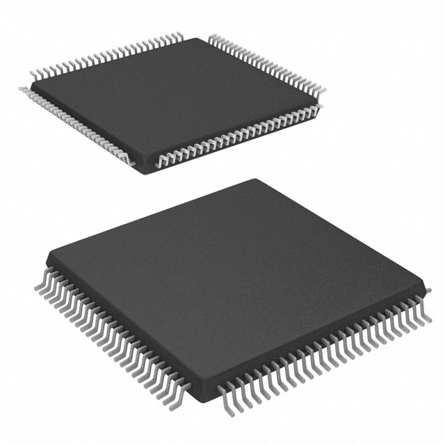
32-bit Arm Cortex-M0+ with 5V Support, CAN-FD, PTC, and
Advanced Analog
Features
Operating Conditions
• 2.7V – 5.5V, -40°C to +125°C, DC to 48 MHz
Core
• Arm® Cortex®-M0+ CPU running at up to 48 MHz:
– Single-cycle hardware multiplier
– Micro Trace Buffer
– Memory Protection Unit (MPU)
Memories
• 32/64/128/256 KB in-system self-programmable Flash
• 1/2/4/8 KB independent self-programmable Flash for EEPROM emulation
• 4/8/16/32 KB SRAM Main Memory
System
• Power-on Reset (POR) and Brown-out Detection (BOD)
• Internal and external clock options with 48 MHz to 96 MHz Fractional Digital Phase Locked Loop (FDPLL96M)
• External Interrupt Controller (EIC) (Interrupt pin debouncing is only available in SAM C20/C21 N)
• 16 external interrupts
– Hardware debouncing (only available in SAM C20/C21 N)
• One non-maskable interrupt
• Two-pin Serial Wire Debug (SWD) programming, test, and debugging interface
Low-Power
• Idle and Standby Sleep modes
• SleepWalking peripherals
Peripherals
• Hardware Divide and Square Root Accelerator (DIVAS)
• 12-channel Direct Memory Access Controller (DMAC)
• 12-channel Event System
• Up to eight 16-bit Timer/Counters (TC), configurable as either (see Note):
Note: Maximum and minimum capture is only available in the SAM C21N devices.
– One 16-bit TC with compare/capture channels
– One 8-bit TC with compare/capture channels
– One 32-bit TC with compare/capture channels, by using two TCs
• Two 24-bit and one 16-bit Timer/Counter for Control (TCC), with extended functions:
– Up to eight PWM channels on each 24-bit TCC
– Up to two PWM channels on each 16-bit TCC
– Up to four compare channels with optional complementary output
– Generation of synchronized pulse width modulation (PWM) pattern across port pins
© 2021 Microchip Technology Inc.
and its subsidiaries
Datasheet DS60001479H-page
品牌/商标Microchip Technology