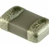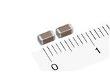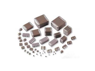

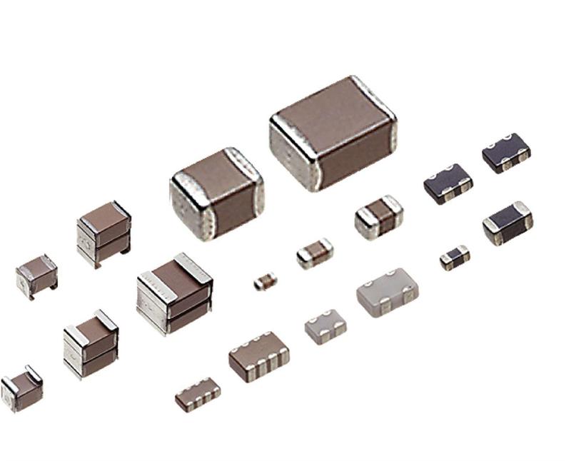

村田 GRM033R71H102KA12D 贴片电容
地区:广东 深圳
认证:
无
图文详情
产品属性
相关推荐
4-3.Correction of Soldered Portion
When sudden heat is applied to the capacitor, distortion caused by the large temperature difference occurs internally, and can be the cause of cracks.
Capacitors also tend to be affected by mechanical and thermal stress depending on the board preheating temperature or the soldering fillet shape, and can be the cause of cracks.
Please refer to "1. PCB Design" or "3. Optimum solder amount" for the solder amount and the fillet shapes.
1. Correction with a Soldering Iron
1-1. In order to reduce damage to the capacitor, be sure to preheat the capacitor and the mounting board.
Preheat to the temperature range shown in Table 3. A hot plate, hot air type preheater, etc. can be used for preheating.
1-2. After soldering, do not allow the component/PCB to cool down rapidly.
1-3. Perform the corrections with a soldering iron as quickly as possible. If the soldering iron is applied too long, there is a possibility of
causing solder leaching on the terminal electrodes, which will cause deterioration of the adhesive strength and other problems.
Table 3
Lead Free Solder: Sn-3.0Ag-0.5Cu
* Please manage Δ T in the temperature of soldering iron and the preheating temperature.
2. Correction with Spot Heater
Compared to local heating with a soldering iron, hot air heating by a spot heater heats the overall component and board,
therefore, it tends to lessen the thermal shock. In the case of a high density mounted board, a spot heater can also prevent concerns
of the soldering iron making direct contact with the component.
2-1. If the distance from the hot air outlet of the spot heater to the component is too close, cracks may occur due to thermal shock.
To prevent this problem, follow the conditions shown in Table 4.
2-2. In order to create an appropriate solder fillet shape, it is recommended that hot air be applied at the angle shown in F
0201
MURATA(村田)
无铅环保型
贴片式
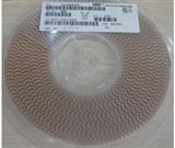
卷带编带包装
普通/民用电子信息产品